 |

THE BELOW LINKS CONTAIN DETAILED AIRLINE, MILITARY JETS, TEST AIRCRAFT, AIRPLANE FACT SHEETS AND AEROSPACE INFORMATION
THE BELOW LINKS CONTAIN AVIATION, MILITARY, AIRCRAFT VIDEOS, PICTURES, FACTS, INFORMATION, AUDIO, HISTORY, MOVIES AND PHOTOS

THE BELOW LINKS CONTAIN FLIGHT TRACKING, AIRPORT INFO, AVIATION PIONEERS, USAF REFERENCES, NTSB FACTS AND AVIATION WEATHER
THE BELOW LINKS CONTAIN INFORMATION ON AIRLINES IN CURRENT SERVICE TODAY AND ALSO BANKRUPT US AIRLINE COMPANIES (DEFUNCT)
GLOBAL POSITIONING SYSTEM (GPS) HISTORY, FACTS, INFORMATION AND PICTURES
 |
 |
The Global Positioning System (GPS) is the only
|
 |
Simplified method of operation
A typical GPS receiver calculates its position using the signals from four or more GPS satellites. Four satellites are needed since the process needs a very accurate local time, more accurate than any normal clock can provide, so the receiver internally solves for time as well as position. In other words, the receiver uses four measurements to solve for four variables: x, y, z, and t. These values are then turned into more user-friendly forms, such as latitude/longitude or location on a map, then displayed to the user.
Each GPS satellite has an atomic clock, and continually transmits messages containing the current time at the start of the message, parameters to calculate the location of the satellite (the ephemeris), and the general system health (the almanac). The signals travel at the speed of light through outer space, and slightly slower through the atmosphere. The receiver uses the arrival time to compute the distance to each satellite, from which it determines the position of the receiver using geometry and trigonometry.
Although four satellites are required for normal operation, fewer may be needed in some special cases. If one variable is already known (for example, a sea-going ship knows its altitude is 0), a receiver can determine its position using only three satellites. Also, in practice, receivers use additional clues (doppler shift of satellite signals, last known position, dead reckoning, inertial navigation, and so on) to give degraded answers when fewer than four satellites are visible.
Technical description
The space segment (SS) comprises the orbiting GPS satellites, or Space Vehicles (SV) in GPS parlance. The GPS design originally called for 24 SVs, eight each in three circular orbital planes, but this was modified to six planes with four satellites each. The orbital planes are centered on the Earth, not rotating with respect to the distant stars. The six planes have approximately 55° inclination (tilt relative to Earth's equator) and are separated by 60° right ascension of the ascending node (angle along the equator from a reference point to the orbit's intersection). The orbits are arranged so that at least six satellites are always within line of sight from almost everywhere on Earth's surface.
Orbiting at an altitude of approximately 20,200 kilometers 12,600 miles or 10,900 nautical miles; orbital radius of 26,600 km (16,500 mi or 14,400 NM), each SV makes two complete orbits each sidereal day. The ground track of each satellite therefore repeats each (sidereal) day. This was very helpful during development, since even with just four satellites, correct alignment means all four are visible from one spot for a few hours each day. For military operations, the ground track repeat can be used to ensure good coverage in combat zones.
As of September 2007, there are 31 actively broadcasting satellites in the GPS constellation. The additional satellites improve the precision of GPS receiver calculations by providing redundant measurements. With the increased number of satellites, the constellation was changed to a nonuniform arrangement. Such an arrangement was shown to improve reliability and availability of the system, relative to a uniform system, when multiple satellites fail.
Control segment
The flight paths of the satellites are tracked by US Air Force monitoring stations in Hawaii, Kwajalein, Ascension Island, Diego Garcia, and Colorado Springs, Colorado, along with monitor stations operated by the National Geospatial-Intelligence Agency (NGA). The tracking information is sent to the Air Force Space Command's master control station at Schriever Air Force Base in Colorado Springs, which is operated by the 2nd Space Operations Squadron (2 SOPS) of the United States Air Force (USAF). Then 2 SOPS contacts each GPS satellite regularly with a navigational update (using the ground antennas at Ascension Island, Diego Garcia, Kwajalein, and Colorado Springs). These updates synchronize the atomic clocks on board the satellites to within a few nanoseconds of each other, and adjust the ephemeris of each satellite's internal orbital model. The updates are created by a Kalman filter which uses inputs from the ground monitoring stations, space weather information, and various other inputs.
Satellite maneuvers are not precise by GPS standards. So to change the orbit of a satellite, the satellite must be marked 'unhealthy', so receivers will not use it in their calculation. Then the maneuver can be carried out, and the resulting orbit tracked from the ground. Then the new ephemeris is uploaded and the satellite marked healthy again.
Calculating positions
Using the C/A code
To start off, the receiver picks which C/A codes to listen for by PRN number, based on the almanac information it has previously acquired. As it detects each satellite's signal, it identifies it by its distinct C/A code pattern, then measures the received time for each satellite. To do this, the receiver produces an identical C/A sequence using the same seed number, referenced to its local clock, starting at the same time the satellite sent it. It then computes the offset to the local clock that generates the maximum correlation. This offset is the time delay from the satellite to the receiver, as told by the receiver's clock. Since the PRN repeats every millisecond, this offset is precise but ambiguous, and the ambiguity is resolved by looking at the data bits, which are sent at 50 Hz (20 ms) and aligned with the PRN code.
This data is used to solve for x,y,z and t. Many mathematical techniques can be used. The following description shows a straightforward iterative way, but receivers use more sophisticated methods.
Conceptually, the receiver calculates the distance to the satellite, called the pseudorange.
Next, the orbital position data, or ephemeris, from the Navigation Message is then downloaded to calculate the satellite's precise position. A more-sensitive receiver will potentially acquire the ephemeris data more quickly than a less-sensitive receiver, especially in a noisy environment. Knowing the position and the distance of a satellite indicates that the receiver is located somewhere on the surface of an imaginary sphere centered on that satellite and whose radius is the distance to it. Receivers can substitute altitude for one satellite, which the GPS receiver translates to a pseudorange measured from the center of the Earth.
When pseudoranges have been determined for four satellites, a guess of the receiver's location is calculated. Dividing the speed of light by the distance adjustment required to make the pseudoranges come as close as possible to intersecting results in a guess of the difference between UTC and the time indicated by the receiver's on-board clock. With each combination of four satellites, a geometric dilution of precision (GDOP) vector is calculated, based on the relative sky positions of the satellites used. As more satellites are picked up, pseudoranges from more combinations of four satellites can be processed to add more guesses to the location and clock offset. The receiver then determines which combinations to use and how to calculate the estimated position by determining the weighted average of these positions and clock offsets. After the final location and time are calculated, the location is expressed in a specific coordinate system, e.g. latitude/longitude, using the WGS 84 geodetic datum or a local system specific to a country.
There are many other alternatives and improvements to this process. If at least four satellites are visible, for example, the receiver can eliminate time from the equations by computing only time differences, then solving for position as the intersection of hyperboloids. Also, with a full constellation and modern receivers, more than four satellites can be seen and received at once. Then all satellite data can be weighted by GDOP, signal to noise, path length through the ionosphere, and other accuracy concerns, and then used in a least squares fit to find a solution. In this case the residuals also give an estimate of the errors. Finally, results from other positioning systems such as GLONASS or the upcoming Galileo can be used in the fit, or used to double-check the result. (By design, these systems use the same bands, so much of the receiver circuitry can be shared, though the decoding is different).
Atmospheric effects
Inconsistencies of atmospheric conditions affect the speed of the GPS signals as they pass through the Earth's atmosphere, especially the ionosphere. Correcting these errors is a significant challenge to improving GPS position accuracy. These effects are smallest when the satellite is directly overhead and become greater for satellites nearer the horizon since the path through the atmosphere is longer. Once the receiver's approximate location is known, a mathematical model can be used to estimate and compensate for these errors.
Because ionospheric delay affects the speed of microwave signals differently depending on their frequency — a characteristic known as dispersion - delays measured on two more frequency bands can be used to measure dispersion, and this measurement can then be used to estimate the delay at each frequency. Some military and expensive survey-grade civilian receivers measure the different delays in the L1 and L2 frequencies to measure atmospheric dispersion, and apply a more precise correction. This can be done in civilian receivers without decrypting the P(Y) signal carried on L2, by tracking the carrier wave instead of the modulated code. To facilitate this on lower cost receivers, a new civilian code signal on L2, called L2C, was added to the Block IIR-M satellites, which was first launched in 2005. It allows a direct comparison of the L1 and L2 signals using the coded signal instead of the carrier wave.
The effects of the ionosphere generally change slowly, and can be averaged over time. The effects for any particular geographical area can be easily calculated by comparing the GPS-measured position to a known surveyed location. This correction is also valid for other receivers in the same general location. Several systems send this information over radio or other links to allow L1-only receivers to make ionospheric corrections. The ionospheric data are transmitted via satellite in Satellite Based Augmentation Systems such as WAAS, which transmits it on the GPS frequency using a special pseudo-random noise sequence (PRN), so only one receiver and antenna are required.
Humidity also causes a variable delay, resulting in errors similar to ionospheric delay, but occurring in the troposphere. This effect both is more localized and changes more quickly than ionospheric effects, and is not frequency dependent. These traits make precise measurement and compensation of humidity errors more difficult than ionospheric effects.
Changes in receiver altitude also change the amount of delay, due to the signal passing through less of the atmosphere at higher elevations. Since the GPS receiver computes its approximate altitude, this error is relatively simple to correct, either by applying a function regression or correlating margin of atmospheric error to ambient pressure using a barometric altimeter.
Multipath effects
GPS signals can also be affected by multipath issues, where the radio signals reflect off surrounding terrain; buildings, canyon walls, hard ground, etc. These delayed signals can cause inaccuracy. A variety of techniques, most notably narrow correlator spacing, have been developed to mitigate multipath errors. For long delay multipath, the receiver itself can recognize the wayward signal and discard it. To address shorter delay multipath from the signal reflecting off the ground, specialized antennas (e.g. a choke ring antenna) may be used to reduce the signal power as received by the antenna. Short delay reflections are harder to filter out because they interfere with the true signal, causing effects almost indistinguishable from routine fluctuations in atmospheric delay.
Multipath effects are much less severe in moving vehicles. When the GPS antenna is moving, the false solutions using reflected signals quickly fail to converge and only the direct signals result in stable solutions.
Ephemeris and clock errors
While the ephemeris data is transmitted every 30 seconds, the information itself may be up to two hours old. Data up to four hours old is considered valid for calculating positions, but may not indicate the satellites actual position. If a fast TTFF is needed, it is possible to upload valid ephemeris to a receiver, and in addition to setting the time, a position fix can be obtained in under ten seconds. It is feasible to put such ephemeris data on the web so it can be loaded into mobile GPS devices.
The satellite's atomic clocks experience noise and clock drift errors. The navigation message contains corrections for these errors and estimates of the accuracy of the atomic clock, however they are based on observations and may not indicate the clock's current state.
These problems tend to be very small, but may add up to a few meters (10s of feet) of inaccuracy.
Selective availability
GPS includes a (currently disabled) feature called Selective Availability (SA) that can introduce intentional, slowly changing random errors of up to a hundred meters (328 ft) into the publicly available navigation signals to confound, for example, the guidance of long range missiles to precise targets. When enabled, the accuracy is still available in the signal, but in an encrypted form that is only available to the United States military, its allies and a few others, mostly government users. Even those who have managed to acquire military GPS receivers would still need to obtain the daily key, whose dissemination is tightly controlled.
Prior to being turned off, SA typically added signal errors of up to about 10 meters (32 ft) horizontally and 30 meters (98 ft) vertically. The inaccuracy of the civilian signal was deliberately encoded so as not to change very quickly. For instance, the entire eastern U.S. area might read 30 m off, but 30 m off everywhere and in the same direction. To improve the usefulness of GPS for civilian navigation, Differential GPS was used by many civilian GPS receivers to greatly improve accuracy.
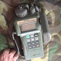
During the Gulf War, the shortage of military GPS units and the ready availability of civilian ones caused many troops to buy their own civilian GPS units: their wide use among personnel resulted in a decision to disable Selective Availability. This was ironic, as SA had been introduced specifically for these situations, allowing friendly troops to use the signal for accurate navigation, while at the same time denying it to the enemy—but the assumption underlying this policy was that all U.S. troops and enemy troops would have military-specification GPS receivers and that civilian receivers would not exist in war zones. But since many American soldiers were using civilian devices, SA was also denying the same accuracy to thousands of friendly troops; turning it off (by removing the added-in error) presented a clear benefit to friendly troops.
In the 1990s, the FAA started pressuring the military to turn off SA permanently. This would save the FAA millions of dollars every year in maintenance of their own radio navigation systems. The amount of error added was "set to zero" at midnight on May 1, 2000 following an announcement by U.S. President Bill Clinton, allowing users access to the error-free L1 signal. Per the directive, the induced error of SA was changed to add no error to the public signals (C/A code). Clinton's executive order required SA to be set to zero by 2006; it happened in 2000 once the US military developed a new system that provides the ability to deny GPS (and other navigation services) to hostile forces in a specific area of crisis without affecting the rest of the world or its own military systems.
Selective Availability is still a system capability of GPS, and error could, in theory, be reintroduced at any time. In practice, in view of the hazards and costs this would induce for US and foreign shipping, it is unlikely to be reintroduced, and various government agencies, including the FAA, have stated that it is not intended to be reintroduced.
One interesting side effect of the Selective Availability hardware is the capability to correct the frequency of the GPS cesium and rubidium atomic clocks to an accuracy of approximately 2 × 10-13 (one in five trillion). This represented a significant improvement over the raw accuracy of the clocks.
On 19 September 2007, the United States Department of Defense announced that future GPS III satellites will not be capable of implementing SA, eventually making the policy permanent.
Applications
The Global Positioning System, while originally a military project, is considered a dual-use technology, meaning it has significant applications for both the military and the civilian industry.
Military
The military applications of GPS span many purposes:
Navigation: GPS allows soldiers to find objectives in the dark or in unfamiliar territory, and to coordinate the movement of troops and supplies. The GPS-receivers commanders and soldiers use are respectively called the Commanders Digital Assistant and the Soldier Digital Assistant.
Target tracking: Various military weapons systems use GPS to track potential ground and air targets before they are flagged as hostile. These weapon systems pass GPS co-ordinates of targets to precision-guided munitions to allow them to engage the targets accurately. Military aircraft, particularly those used in air-to-ground roles use GPS to find targets (for example, gun camera video from AH-1 Cobras in Iraq show GPS co-ordinates that can be looked up in Google Earth).
Missile and projectile guidance: GPS allows accurate targeting of various military weapons including ICBMs, cruise missiles and precision-guided munitions. Artillery projectiles with embedded GPS receivers able to withstand accelerations of 12,000G have been developed for use in 155 mm howitzers.
Search and Rescue: Downed pilots can be located faster if they have a GPS receiver.
Reconnaissance and Map Creation: The military use GPS extensively to aid mapping and reconnaissance.
The GPS satellites also carry a set of nuclear detonation detectors consisting of an optical sensor (Y-sensor), an X-ray sensor, a dosimeter, and an Electro-Magnetic Pulse (EMP) sensor (W-sensor) which form a major portion of the United States Nuclear Detonation Detection System.
History
The design of GPS is based partly on the similar ground-based radio navigation systems, such as LORAN and the Decca Navigator developed in the early 1940s, and used during World War II. Additional inspiration for the GPS came when the Soviet Union launched the first Sputnik in 1957. A team of U.S. scientists led by Dr. Richard B. Kershner were monitoring Sputnik's radio transmissions. They discovered that, because of the Doppler effect, the frequency of the signal being transmitted by Sputnik was higher as the satellite approached, and lower as it continued away from them. They realized that since they knew their exact location on the globe, they could pinpoint where the satellite was along its orbit by measuring the Doppler distortion.
The first satellite navigation system, Transit, used by the United States Navy, was first successfully tested in 1960. Using a constellation of five satellites, it could provide a navigational fix approximately once per hour. In 1967, the U.S. Navy developed the Timation satellite which proved the ability to place accurate clocks in space, a technology the GPS relies upon. In the 1970s, the ground-based Omega Navigation System, based on signal phase comparison, became the first world-wide radio navigation system.
The first experimental Block-I GPS satellite was launched in February 1978. The GPS satellites were initially manufactured by Rockwell International (now part of Boeing) and are now manufactured by Lockheed Martin (IIR/IIR-M) and Boeing (IIF).
Timeline
In 1972, the US Air Force Central Inertial Guidance Test Facility (Holloman AFB) conducted developmental flight tests of two prototype GPS receivers over White Sands Missile Range, using ground-based pseudo-satellites.
In 1978 the first experimental Block-I GPS satellite was launched.
In 1983, after Soviet interceptor aircraft shot down the civilian airliner KAL 007 in restricted Soviet airspace, killing all 269 people on board, U.S. President Ronald Reagan announced that the GPS would be made available for civilian uses once it was completed.
By 1985, ten more experimental Block-I satellites had been launched to validate the concept.
On February 14, 1989, the first modern Block-II satellite was launched.
In 1992, the 2nd Space Wing, which originally managed the system, was de-activated and replaced by the 50th Space Wing.
By December 1993 the GPS achieved initial operational capability.
By January 17, 1994 a complete constellation of 24 satellites was in orbit.
Full Operational Capability was declared by NAVSTAR in April 1995.
In 1996, recognizing the importance of GPS to civilian users as well as military users, U.S. President Bill Clinton issued a policy directive declaring GPS to be a dual-use system and establishing an Interagency GPS Executive Board to manage it as a national asset.
In 1998, U.S. Vice President Al Gore announced plans to upgrade GPS with two new civilian signals for enhanced user accuracy and reliability, particularly with respect to aviation safety.
On May 2, 2000 "Selective Availability" was discontinued as a result of the 1996 executive order, allowing users to receive a non-degraded signal globally.
In 2004, the United States Government signed a historic agreement with the European Community establishing cooperation related to GPS and Europe's planned Galileo system.
In 2004, U.S. President George W. Bush updated the national policy, replacing the executive board with the National Space-Based Positioning, Navigation, and Timing Executive Committee.
November 2004, QUALCOMM announced successful tests of Assisted-GPS for mobile phones.
In 2005, the first modernized GPS satellite was launched and began transmitting a second civilian signal (L2C) for enhanced user performance.
On September 14, 2007, the aging mainframe-based Ground Segment Control System was transitioned to the new Architecture Evolution Plan.
The most recent launch was on March 15, 2008. The oldest GPS satellite still in operation was launched on July 4, 1991, and became operational on August 30, 1991.
© AviationExplorer.com - The Website For Aviation Enthusiasts |